Suzuki Forums banner

Suzuki Vitara 1992- ECU help needed!

54K views 143 replies 7 participants last post by  Bex  
#1 ·
Hello to everybody!
My compliments for this wonderfull forum website!

My brother has a Suzuki Vitara JLX TBI -1991 - 1.6L -8V manual and 4WD (European - Germany), which has its ECU got crazy and as I am an
electronics-addicted, I am trying to get it repaired (If I will manage).
The car ECU is the same used for the Geo Tracker G1 - with part number
JE331B604A.

Background:
The car on one day did not start anymore, and on switching ON ignition
after the initial CEL, the main relays started to get crazy with continuous
clicking. The ECU had already been fixed some years before (with not very elegant soldering in my opinion), from a "I know everything" type of mechanic,
replacing the C111 cap and basically cracking the 1206 SMD bypass ceramic cap C48.

As I read the fantastic David Ruberg ECU repairs page, I have learned that the weak points of this board are all the poor Rubycon caps. I have indeed
replace C103, C101 and C111 and replaced the C48 with a ceramic 1206 SMD 1000pF one (as I did not have bigger value size). Unfortunately I did not find in my local store the C105 Tantalum polarized cap. However, waiting from the C105 new cap purchased online, I have decide to try on the car the ECU fixed up this point.

QUESTION:
On first trial the board did not wake up at all! All the via-holes
of the replaced caps are jumped to be sure to not miss main reference 5V on the board. However, pin A23, and on the diode D107 cathode (btw the diode is not shorted) I do NOT have the 5V reference voltage.

1) If the board is a 3-layer one, could it be that I am missing some connection inside a acid damaged via-hole with some dipped layer?

2)I doubt it, but could it be that a wrong value of C48 could cause some shorting? As I do not have a cap meter, do you know its value?

3) To understand better the 5V trouble, where is generates the 5V reference?

4) Any other idea to know where to check for stupid errors?

Thanks a lot to everybody :D

Cheers
Eon
 
#30 ·
Sorry guys,
I was away for some hours......the car is parked in a repair shop, and I cannot go there during the night (here is 0:14 AM) to read the engine tag, and all the possible car ID.....

Tomorrow, I will check that and when you will wake up, you will have it......

Thanks anyway.

Cheers
Eon
 
#33 · (Edited)
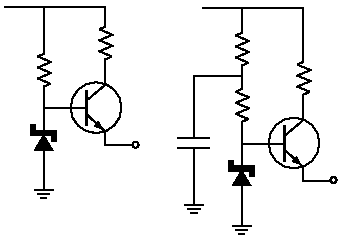
The 5V regulator circuit should look similar to the pic on the left:
Image


There shouldn't be any components that are impossible to replace so it should always be repairable. The zener needs to have good stability and a low temperature coefficient to maintain an accurate supply across the rated temperature range.
 
#34 ·
Thanks alot Rhino......
I hope to manage to find the problem.......at leats for
all these good informations I have got from you guys.....

*Your schematics:
To which transitor it refers? Q100?
Because if it is Q100, I tried to follow its base pin, and it goes to
the pin2 of the hybrid IC7, and nowhere else. Only if it is mounted
R2 (which to my board is NC), this connection in addition
to IC7 (pin2) will be connected also to the junction between R235
and D107 cathode....
is that right or am I looking to the wrong board components?


*Body TAG:
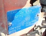
I found finally the body tag of the car (in attachment)....

I guess the numbers you were asking for are:

Chassis NO. = 2S3TA01C000515071
Engine = G16A
Market Code= FAE625M22

So in case this board will not come back alive, which PN I shall
look for on the market?

Thanks alot!

Cheers
Eon
 

Attachments

#36 ·
Thanks alot Rhino......
I hope to manage to find the problem.......at leats for
all these good information I have got from you guys.....
yes its fun hacking here. for sure. and starves scalpers, yes.

*Your schematics:
To which transistor it refers? Q100?
Because if it is Q100, I tried to follow its base pin, and it goes to
the pin2 of the hybrid IC7, and nowhere else. Only if it is mounted
R2 (which to my board is NC), this connection in addition
to IC7 (pin2) will be connected also to the junction between R235
and D107 cathode....
is that right or am I looking to the wrong board components?
no , i was trying , INEFFECTIVELY to discover Q100 purpose.
and since my IC 10 is missing ( gross incompetence during move)
i can not find the true actual 5vdc reg. but i suspect its on IC10
as one other poster here last week fond a blown trace on IC 10 hybrid.

my test board, stripped of connectors.
had bad PS 5v. and is still bad.
the q100 on my board is good.
but IC10 is missing, and pin14 is 5v pin, and may be the output of the 5vdc PS. (my best guess , lacking the part) sorry


*Body TAG:
I found finally the body tag of the car (in attachment)....

I guess the numbers you were asking for are:

Chassis NO. = 2S3TA01C000515071
Engine = G16A
Market Code= FAE625M22 (MIKE 22 car yes!!!)

So in case this board will not come back alive, which PN I shall
look for on the market?

Thanks alot!

Cheers
Eon
yes , let me research Mike 22 , VITS !

cheers to you and all others.


i will make up a full list off all ECUs used in the genre.

later,

it might be possible to fix your ecu, depends an the real cause
of power loss
1: supply blew up
2: shorted load.
3: blown trace on main board.
 
#43 ·
as we in the real world ,dont have Mitsubish data of any kind.
The Mitsu numbers aren't (except in this case) usually very useful, I only use them to ensure that the ECU has the correct PCB fitted. The numbering is pretty easy to deduce once you've seen a few. The PCB has its part number stamped on the connector after it has been assembled. Have a look at your pics - the connector is stamped 1281M. Now check the sticker on the front it has the Suzuki part number and underneath the Mitsu part number E2T41281M. All Mitsu ECUs seem to have a E2T4 number so to find the Suzuki part number of an unknown board just prefix the number on the connector with E2T4 and Google it.
The Denso ECUS use a very similar system.
 
#37 ·
CAMI made, from Canada to EU.

wow and good. better docs.

as you can see SUZUKI made cars in CAMI (not just CHEV ,gm ,geo)
proof !
thanks for tag, i collect them for others.....

FOUND IT in EPC.
type 2
EC production in CAMI for EURope.
sn 5100000 E22 canvas top product of canada.
bingo's all.
break down 2:
FAE625M22
FAE = canvas+SE416-+ the E= 4door canvas top. (called 5door in EU)
62=1.6L 8v , 5sp tranny
5= JLX grade
and 22 - Market 22 , built to German std.

better we need the number stamped on the ECU main connector
44271T2 ? or the like
 
#38 ·
CAMI made, from Canada to EU.

wow and good. better docs.

as you can see SUZUKI made cars in CAMI (not just CHEV ,gm ,geo)
proof !
thanks for tag, i collect them for others.....

FOUND IT in EPC.
type 2
EC production in CAMI for EURope.
sn 5100000 E22 canvas top product of canada.
bingo's all.
break down 2:
FAE625M22
FAE = canvas+SE416-3dr+ the E= 4door canvas top. (called 5door in EU)
62=1.6L 8v , 5sp tranny
5= JLX grade
and 22 - Market 22 , built to German std.
now find ECU.


60A70 , is japan made ECU. ( yes)
56B30 is cami made. quote MT E22 product of canada.

so i was right ,same ECU. and is ubiquitous here, vast number exist in N.America.
ebay using USA prefix.

i will capture your page and post it next .
this car is indexed as SE416- 10 ( 1 of 28)
shows 12 throttle bodies word wide this model , wow.
i looked at smog page and its same as 91 here
and same EGR, and VSVs, only one smog page, a good sign.
I think 56B30 is a GO.

Image
 
#39 ·
in the world of vits. all this era and (non USA we have only 1, blissful huh)

there are 3 type motors. or more.

carb
TBI flavors. some of these have diffr, Distributors. ( a warning)

and MPI.

The v code on my EPC page is V - van 4dr (here) 5dr ROTW (rest of the world)
the C code is canvas, rag top 2 door. 2 dr (ROTW)

the E codes are markets.

that should help you under stand the EPC> (electronics parts cat)
 
#41 · (Edited)
OK so someone has swapped your ECU or at least your PCB with a euro ECU, now maybe we know why the sticker was removed. I wouldn't worry too much about that, it may well run better on ther Euro ECU, it would be interesting to have a back to back comparison. The 56B30 is readily available so I would look at getting one of those as a replacement/spare.
If you fix the B70 and want to try it in US spec then you should just be able to move the resistor from the R302 position to the R301 position. You should also change the part number on the connector from 1371M to 1271M to avoid further confusion!
I'm pretty sure that the 5V regulator is Q104 which is the transistor in the centre of the PCB as I suggested earlier.
 
#42 ·
OK, I found a 56B80 (EU version of the 56B40 that Kick posted), Kick has the correct transistor, it is Q100 and you are correct that it is driven by IC7. This is a hybrid, its possible to replace some of the components on it but the centre chip is probably custom and would need special equipment. We could rework the circuit to get 5V but there may be a watchdog timer on IC7, I would have to check.
Do you have 12V on the emitter of Q100? is there any sign of damage to the hybrid? Do you have 12V on pin 3 of IC7, this is the supply to the hybrid.
 
#44 ·
Hello Guys!
And thanks alot for the great support!

NEW BOARD:
So, the 56B30 shall work fine on my car, right?
Thanks for even check deals on ebay.....BTW which price shall be a
good deal for such a board?


REPAIRING THE ONE I HAVE:
So to understand correct, this board is a B70 type? And you guys are
sure that the ECU board was swapped?

My main problem to test this board, is to test it in unconfortable
position and very little space to work (as short cables to teh ECU) in the clutch pedal area of the car.....so to check voltage, and find where a broken trace would be, is it ok to place +12V on pin B1/B7 and GND on B2/B10 on my test home-lab with a external 12V power supply?

So, to prevent oscillations, fake open circuit response of the board, do I need to have necessarily loads on some outputs of the board and have terminated to GND/50Ohm some inputs? Which one would be a very simple ECU test-set to rapidly check where this power lines is interrupted? Here
I need only to get awake the board, not funcionalities for the moment....

Thanks lot.

Cheers
Eon
 
#45 ·
yes, perfect
dont need loads. unit will stack DTCs for open inputs, no big deal.
my dead ecu page
see this link for power

http://kick-fix.com/ECU/ecu-8v-sig-list/e76.jpg


i made both ecu's pages today for 8v and 16v. see below 8v


check with VM at Q100 C pin. if not 5v, either there is a short on the 5vdc buss or, and open, or the hybrid is blown.
i believe the hybrids are not for sale on plant earth by and LARGE but if you had a spare ecu that was like destroyed, then you could cannibalize it ,but who has that.?
you might find one here by 1 user here, but there is no continuous SUPPLY so I don't list them in my page. Makes sense right?
No where on earth means , OTC, over the counter (like at DIgikey.com or Mouser.com etc.) but Cannibalism rules the roost in KICK LAND, no lie.

Im checking this board carefully and the 16v thanks to one other posters , help.

Image
 
#46 ·
there are no guarantees in life.

only the parts list.

all others ,hire an engineer.

but for $50 bucks, what's the deal?

to me , id be on cloud 9 with so many spares floating about. ( in the future, who knows>?, maybe less, may be scalpers ) get em while they are hot and cheap.
 
#47 ·
That board is a B70, no doubt at all. IC7 doesn't usually get damaged it is normally the components that supply 12v to pin 3 that get damaged. If I can a PCB that is badly burnt then I just replace it with a refurbished one and keep the old one for spares. I have plenty of hybrids, they are common to all the 8V Vits through to 2001.
 
#48 ·
Thanks alot kick!
nice job with all the informations! I really apprecciate the schematic! :D

As soon I will spare time from my work, I will check the board with +12V B1/B7 and GND on B2/B10 and come back with test results.....

Rhino,
sounds very good that you have spares hybrids.....for example do you have
both IC7 and IC10? And at which price?

btw, I remember now.....the board when I got in my hand first time, the hybrid IC10 was bended towards the Q100 Q102 heat sink....I guess the repair shop guy (as the car was sent there when was totally dead, and the ECU was unmounted by the repair shop guy) which wasn't too carefull with it....so I simply bent that back.....very delicately......at glance does not seem to be any trace-crack......I hope is not there the dilemma....
any similar experience?

regarding B70 on ebay the PN 56B70 refers only to ECU of Nissan Sentra.....
so, in case a new board is the last solution, the alternative for getting a new one are:

1) 33920-56B30
2) 33920-56B40 (For AT - I found lower price than B30 - if Kick ensures that they shall run ok on my car, I could consider to buy one of those instead)
2) xxxxx -xxB70 ?? which PN I shall use here?

Thanks alot :)

Cheers
Eon
 
#51 ·
Rhino,
sounds very good that you have spares hybrids.....for example do you have
both IC7 and IC10? And at which price?
Cheers
Eon
PM me if you need them. The 56B40, will work although the autos have different firmware to the manuals it isn't really noticable. The B80 is also a possibility if you can source one cheaply. That can be converted to a B40 by removing R302. The problem with eBay US is that most vendors won't ship outside mainland US and those that do want silly prices. On top of that they don't always marked the package as a used item so you may have to pay 20% VAT. There are some good bargains to be had there though.
 
#49 ·
ebay what country there is a page for every country.?
nice you found hybrids of only source on planet earth, nice.

most PN ECU are not sold here, USA> ( we only have 1 ECU for TBI MT no others) {excepted on later years with special EGR}

no assurances only ideas.

keep the global view.
car is bad. ecu bad.
used parts hard to find.? no?
surely any expert ( and smog man) will tell you (correctly) that only the( number on ECU lid) fits your car and now you have the actual parts list and no more guessing the choices.
yours Number was lost. last choice is parts, list on post 37.

but you might find and open or a short or bad Hybrid on ECU. if you look, and im SUre you will and will find the real cause.


my recommendations are only ideas, things to try.

did you even see post37.?
that is the official SUZ parts list showing exactly what fits YOUR car.
I dont know what ecu fits your car, and neither do you, so.... one can only look at post 37 and see.
what ecu you have i have not a clue.
nor do i know if is original, now way to tell that, from a sticker. (missing?)
( nobody posts , lists Suzuki. Geo and Mitsubishi pn cross-references. show me!) ( ive scoured the earth)


GOOGLE search your ECU actual pn and see all the hits. i see 5000
Ebay search , 10 or more posted and i know for a fact those suppliers do not list their full inventory, you must click , ask seller a question..........
 
#50 ·
my b70 was a typo
60A70,, im not sure what a 60A70 is.

not sure why one ECU, dont like 4 door. car.
not at all.
or if it's was just a factory trend. ( sometimes 2 ECU are same but are PN diffr, due to diffr factory source , for TRACKING reasons)

Parts lists can be weak, and dont show motor type, in example. (in this case , see it) it's missing. but on other years, and such is clearly shown in the EPC.

sometimes it does other times not. sadly.

so , WYSIWYG.
 
#52 ·
Hello guys!
Im back and finally I had some spare time to test the board.

I have checked the board on my small lab test jig, powering the board with the +12V supply between pin B1 and B2. All IC: IC7, IC10, IC2, IC1, has the correct 12V voltages and the 5V reference is correct everywhere it shall be so. At least it does not seem that there a critical short somewhere in the board.

I have used some of the documentation provided by Kick and checked
all the A- and B- connector pin signals.
Obviously, as the board is not connected to the rest of the car, some of those signals are not correct compared with what is written in the document "ECM and its circuit check" (taken form the "Electronic Fuel Injection System 6E-75").

I will go back to the repair shop this afternoon to check on the A- B- connector side, all the resistance which I shall have as written on the same document mentioned above. However, I am not expecting to find some surprising news.

Last time I connected the ECU to the car, as a result the the board seemed totally dead. The 12V seemed at least present around the cable connector as all the car-fuses where in places working, but no Check Engine Light came up at all. Obviously the car didn't even think to start.

At this moment my conclusion/questions are:

1) If the board seems healty on the lab test, with all the power signals and reference present, it could be that one of the hybrids is damaged (however no damages are noticeable on those)?

2) It could be instead the board is healty, and something else on the car is giving troubles. For example, if the CEL is not coming up, could it be that some of the input signals which the board shall receive are not provided and then the CEL does not come up?

3) As I am not a mechanic car expert, on the schematics by Kick, which signal is vital to perform the CEL at car start?

4) I don't have a scope available to check the injector + (B8) and - (B17) pulsed signals. Is this signal started after the CEL check, or the CEL check needs the ijector (TBI) powered and driven to have the CEL ON?

Sorry for these many questions, but I need to conclude this analysis, as if the board is not repairable, I have to start to check for a spare one rapidly.

The best it could be to try the board on another identical car, and at least
understand if the ECU works or not and then figure out where is this annoing problem.

I will be back with more news after the new test on the car today.

Thanks for help anyway.

Cheers
Eon
 
#53 ·
Suzuki Vitara JLX TBI -1991 - 1.6L -8V
IS THIS CAR FITTED WITH IMMO ?????? immobilizer?

Hello guys!
Im back and finally I had some spare time to test the board.

I have checked the board on my small lab test jig, powering the board with the +12V supply between pin B1 and B2. All IC: IC7, IC10, IC2, IC1, has the correct 12V voltages and the 5V reference is correct everywhere it shall be so. At least it does not seem that there a critical short somewhere in the board.
Ok 5vdc , a good sign

I have used some of the documentation provided by Kick and checked
all the A- and B- connector pin signals.
Obviously, as the board is not connected to the rest of the car, some of those signals are not correct compared with what is written in the document "ECM and its circuit check" (taken form the "Electronic Fuel Injection System 6E-75").

I will go back to the repair shop this afternoon to check on the A- B- connector side, all the resistance which I shall have as written on the same document mentioned above. However, I am not expecting to find some surprising news.

Last time I connected the ECU to the car, as a result the the board seemed totally dead. The 12V seemed at least present around the cable connector as all the car-fuses where in places working, but no Check Engine Light came up at all. Obviously the car didn't even think to start.

At this moment my conclusion/questions are:

1) If the board seems healthy on the lab test, with all the power signals and reference present, it could be that one of the hybrids is damaged (however no damages are noticeable on those)?

The CEL must come on , or the ECU is no good.
Assuming (of course) power is applied, and the CEL lamp is correct size and connected, do not use a 1157 lamp, do NOT.
if not , ECU needs to be Swapped out. or sent to good repair shop.
ask.


2) It could be instead the board is healthy, and something else on the car is giving troubles. For example, if the CEL is not coming up, could it be that some of the input signals which the board shall receive are not provided and then the CEL does not come up?
NO, this is not true, only power is needed !!!

3) As I am not a mechanic car expert, on the schematics by Kick, which signal is vital to perform the CEL at car start?
POWER ONLY read the section called TAKE THE 3 TESTS>?

4) I don't have a scope available to check the injector + (B8) and - (B17) pulsed signals. Is this signal started after the CEL check, or the CEL check needs the ijector (TBI) powered and driven to have the CEL ON?
Dont bother , ECU is dead , injection is last thing to happen.
Injection takes (brains) Power, CMP, spark and no WOT signalling.
you must be able to crawl before walk, CEL MUST GLOW.

Sorry for these many questions, but I need to conclude this analysis, as if the board is not repairable, I have to start to check for a spare one rapidly. YOUR ECU is bad.


The best it could be to try the board on another identical car, and at least
understand if the ECU works or not and then figure out where is this annoing problem. , YOUR ECU is Bad.

I will be back with more news after the new test on the car today.

Thanks for help anyway.

Cheers
Eon

stop do not pass go , do not collect $200 (monopoly game joke)
STOP, Get CEL to glow.
do not proceed, until the CEL glows at key , on.

IMMO, will flash if it is blocking ECU>
I have a IMMO book now if you have it and need it.
i got the full service manuals in PDF this.

The CEL in usa can be blocked by NAG (federal 48 uSa only)
and in other countries that have the IMMO option the CEL is blocked or
does funny things if IMMO is blocking.
i can send the pages if you need it.

cheers.
 
#55 ·
ah, i re-read some of your posts.
yes your car is the TAG less ECU car.

1st one ever here for that ,

if you need ECU ask rhinoman for proper ecu number
then GOOGLE for it in EU , using (for example: " 33920-56B00" or the like (your end suffix will be different) with out the quotes.

just let google find the suppliers. there are many in EU, i see them all the time
in my searches.
major exchange houses.

in USA i see NOW , many stores offering for the first time rebuilt ECU for SIDEKICK.
(this is for viewers benefit.)
 
#57 ·
Hello Kick!
Im back from an afternoon test episode with the car....

Results are:

1) The board with A- and B- connector plugged in, does not give sign.

2) I checked the resistances on the A- and B- connectors side with ignition off, and they are correct as specified in your resistance test documentation.

3) I have discovered, that the board does not get the +12V power supply
from the B- connector. It seems that the +12V does not arrive on the B-connector from the cable side behind somewhere. However, I double check with the repair shop guy and nothing is noticeable on the main connection cables.

4) I have taken a +12V power supply line (by the same car battery of course) and I have directly connected it to the ECU pin B1 during it was plugged to the car. THEN, the CEL came UP immediately. However, the car did not start anyway.

With this set-up I checked:

a) The ECU has all main power supply signals, and the +5V reference everywhere.

b)The injection worked as suddenly a strong benzin smell came out, but the pump does not work as the fuel inlet pipe when disconnected from the engine does not manage to push out a compressed fuel flow.

c) it seemed that the pump main relay is not excited to give power to the fuel pump. I do not understand it the reason.
So far, we do not have a similar car, to see if the trouble is still sitting
inside the ECU or somewhere else in the car.

CONCLUSION:

- We did not considered to check the fuel-pump and its power supply as it is under the tank area and it take too much work to reach it. However, the repair shop guy told me that when he got the car initially (3 weeks ago), even if the two relays were acting crazy, the pump was giving the correct fuel pression. Something changed after then, but I do not know where.

- As, we do not have other better idea, I will try to purchase a spare ECU hoping to see some good results.

If you have any other better suggestions, you are welcome to answer.
Thanks.

Cheers
Eon
 
#58 ·
virtual sig: uzuki Vitara JLX TBI -1991 - 1.6L -8V manual and 4WD (European - Germany a real market E22 car.)
i cant under stand your post! but is clear enough for me. and contradicts.....????

you need to stop. ( i see you hot wired the ECU.)
why do that ?, why not stop and fix this horrible first ORDER failure ??????? ( show the voltages below and i will find problem)

in the real world you can not fix everything all at once, only martha stewart can.
LOL..

back to post 1. day 1 square 1

CEL off , FSM says. paraphrasing and affirming......

1: make sure the 3 fuses to the ECU are good.
measure the voltage at both sides of the fuse, is best practice or chase tail.

2: make sure you have:
12v these pins, you keep forgetting to say what pins are dead, mark the pin# on the out side of the ECU can ,if you cant understand them ?

see the power pins b1 ,b7 and b9 ( all must have power KEY ON ) . B side is is closest to C111 main cap and is GREEN. Geo uses other numbers... forget Geo. jive.
if not , give me voltage on B15.
if zero volts, Main relay is blown ( give me voltages on all pins of MAIN relay , key on)????

if 12vdc, B15 then ECU is blown or ground is missing on ecu.
if ground is suspected. then

with VM minus lead to battery minus LUG (long wire it)
take read VM red lead (20vdc range) and measure.
b2 ,b3 and b10 AT ECU.
must read 0.5vdc or less KEY ON. This is GROUND SPEC.on all suz. grounds. 1/2volt MAXimum allowed.

do not do anything else. see next post for a plan.

(btw the fuel pump only runs for 3 second key on) dont confuse this fact.


dont buy anything.
you keep refusing to repair the first order failures.
1: CEL is out, FIX THAT.
2: then you discover power loss and in stead of fix that you advance beyond that.

do not run the car hot wired. its not safe.
sure it might start but id dont care,
the ecu makes car safe to run so it cant catch fire.
do not defeat those features.


your car for sure has a primarly power fail.
looking below you see i added the actual diodes the turn on the MAIN.
it is possible to blow that 1 diode and make MAIN fail.
USA cars have this diode im told other VIts have a diff. way.


Image
 
#62 ·
Ok Kick,
my answer below in red:

virtual sig: uzuki Vitara JLX TBI -1991 - 1.6L -8V manual and 4WD (European - Germany a real market E22 car.)
i cant under stand your post! but is clear enough for me. and contradicts.....????

you need to stop. ( i see you hot wired the ECU.)
why do that ?, why not stop and fix this horrible first ORDER failure ??????? ( show the voltages below and i will find problem)

ok Kick, thank you for the reccommendations, but I am used with alot of electronics from before, so if I decided to hot wire the ECU is because:
a) The ECU did not get any +12V on pin B1/B7 and it may be the I could have a trouble somewhere before the ECU.

b) I have already tested the board on my lab and things worked correctly at least with DC signals.

in the real world you can not fix everything all at once, only martha stewart can.
LOL..

back to post 1. day 1 square 1

CEL off , FSM says. paraphrasing and affirming......

1: make sure the 3 fuses to the ECU are good.
measure the voltage at both sides of the fuse, is best practice or chase tail.

The first thing I have done was to check all fuses. They are all good.

2: make sure you have:
12v these pins, you keep forgetting to say what pins are dead, mark the pin# on the out side of the ECU can ,if you cant understand them ?

When I say there is no power supply , of course I was meaning ECU pin B1 and B7. They do not get any power supply. So what else to check if the ECU does not come alive at all as there is no power supply at all to understand something??

see the power pins b1 ,b7 and b9 ( all must have power KEY ON ) . B side is is closest to C111 main cap and is GREEN. Geo uses other numbers... forget Geo. jive.
if not , give me voltage on B15.

Without hot wire, of course B1, B7 and B9 are at 0V. I did not measure B15 with the ECU plugged-in and ingnition ON. However, it is not easy to stick a VM probe on the cable connector side as they are strongly tight to reach contact with the wire copper, and it is not easy either to measure B15 on the PCB side as B15 is under the B1-B8 connector leads.
if zero volts, Main relay is blown ( give me voltages on all pins of MAIN relay , key on)????

I have to do that. not sure when I can go back there.

if 12vdc, B15 then ECU is blown or ground is missing on ecu.
if ground is suspected. then

with VM minus lead to battery minus LUG (long wire it)
take read VM red lead (20vdc range) and measure.
b2 ,b3 and b10 AT ECU.
must read 0.5vdc or less KEY ON. This is GROUND SPEC.on all suz. grounds. 1/2volt MAXimum allowed.

do not do anything else. see next post for a plan.

(btw the fuel pump only runs for 3 second key on) dont confuse this fact.


dont buy anything.
you keep refusing to repair the first order failures.
1: CEL is out, FIX THAT.
2: then you discover power loss and in stead of fix that you advance beyond that.

I dont want to buy anything......I will try to do again the power test. Can you tell me how easy to understand which one is the MAIN relay from the Fuel pump one as they are exacly the same? And cable between relay and ECu connector change color and they taped all togheter? THANKS

Eon


Image
 
#59 ·
plan:
1: do not assume anything, lets fix the problems 1 at a time.
no martha stewart baby on hip vacuuming and making dinner for bum husband.!!! LOL
2: lets first get MAIN UP. (relay closed and power to all majors)

3: once this small goal is achieved (CEL is on now , wow you have power for the first time.

4: key on CEL comes on (does it flash out 12 , with diag jumper in place?)
5: key one (person 2.) you person 1 listen at gas cap hole , cap off
buzzzz for 3 seconds, stop.

if yes to #5 , the ECU is operating the Fuel pump relay as designed.
good. if not report.

if you hear the buzz check fuel pressrue for 35.6psi. Minimum 3 to 5 key on , no start.

if pressure is good.
then try to start car.
if car floods.
you need to do all 5 fuel pressure tests.
if the leak down fails then an injector is leaking or 1 is gated on full time by bad ECU.

doing the NOID test now is best.

there that is plan,
i can assume you have a strobe light and know how to test for spark timing
cranking, can you?

ok , we can fix it. ECU really wants to start car.
you need only a good ecu and good wires and a working pump.