Suzuki Forums banner
21 - 35 of 35 Posts
Hi all,

I have an Ignis (y 2022, EU model) bought second-hand. It came with Android multimedia device, because apparently Suzuki did not ship the original Bosch SLDA at time of buying due to lack of chips.

Now, I managed to buy the original Bosch multimedia device but I don’t know where to attach the original mic (wiring goes from the interior lighting to the SLDA) since all of the ports on my SLDA are used.

If someone could post an image of the original wiring maybe I could figure it out.
I am pretty sure it was modified to fit the Android device.

Any help would mean a lot.

Thanks.
Did u get sorted?
 
Hey Mike,

You will need this connector (https://car-solutions.com/en/camera-connection-cable-for-suzuki/) if you have a yellow chinch connector.
For the mic, I need to catch my friend (electrician) to test which wire is what. Then I will try to connect it and get back with the results.

I fixed it , i have used this connector
Worked like charm, the camera is turned on when you put the gear in revers.
The microphone in next, will have to solder the cables when it gets a bit cooler. It is boiling hot in the car at the moment :)
Thank you guys for the advice.
 
Discussion starter · #27 ·
Great news. Glad we could help. If you manage to fix the mic before me feel free to post the solution. My electrician is a “ghost” ;) If you find the original connector for purchase, please share the URL, for the cables as well ;)

I fixed it , i have used this connector
Worked like charm, the camera is turned on when you put the gear in revers.
The microphone in next, will have to solder the cables when it gets a bit cooler. It is boiling hot in the car at the moment :)
Thank you guys for the advice.
 
Here's a picture out of my SZ5 in case it helps. The colours DO match on this harness and I checked with a multimeter and the two grey wires connect together, suggesting they are earth making the 4 into 3 wires sensible. If I was guessing maybe red is power, grey is ground, yellow is signal.
Image
Image
 
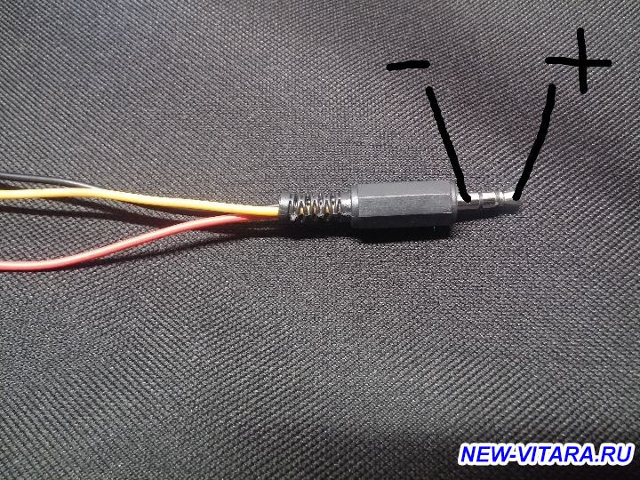
The yellow cable is the +5V power supply.
The secondary gray cable is grounding.
The red cable is the + signal.
The last gray cable is - signal.
I found the microphone connection only on the Russian website.
 
Discussion starter · #32 · (Edited)
Seems like I missed a few answers. Sorry for not replying. Great info! In the meantime I digged up some instructions for Kizashi but it seems it could do the trick. It has an interesting note written at the very bottom of the image attached. And I realised I already have the connector in place on the back of the unit. So maybe just needs a "patch" to the interior light board which would be great.

Image
 
Discussion starter · #33 ·
New update, removed the interior light but the wires are missing or they are under the top surface and I am not willing to risk it. Back to square 1. I will try to follow the connector from the back of the unit.
 
If you have to make your own microphone connector for the SLDA I believe the connector you need at the radio end is 1379658-2 by AMP/TE. If you make this then I guess you could use any cheap 5v microphone on the end of it and put it somewhere more convenient. Then you wouldn't have to lift the head lining if it's not there.
 
Discussion starter · #35 ·
If you have to make your own microphone connector for the SLDA I believe the connector you need at the radio end is 1379658-2 by AMP/TE. If you make this then I guess you could use any cheap 5v microphone on the end of it and put it somewhere more convenient. Then you wouldn't have to lift the head lining if it's not there.
Tnx for the tip for the connector. Genuine connector is G231 but I couldn’t find it anywhere on the net.
 
21 - 35 of 35 Posts