Suzuki Forums banner
61 - 80 of 144 Posts
Discussion starter · #62 ·
Ok Kick,
my answer below in red:

virtual sig: uzuki Vitara JLX TBI -1991 - 1.6L -8V manual and 4WD (European - Germany a real market E22 car.)
i cant under stand your post! but is clear enough for me. and contradicts.....????

you need to stop. ( i see you hot wired the ECU.)
why do that ?, why not stop and fix this horrible first ORDER failure ??????? ( show the voltages below and i will find problem)

ok Kick, thank you for the reccommendations, but I am used with alot of electronics from before, so if I decided to hot wire the ECU is because:
a) The ECU did not get any +12V on pin B1/B7 and it may be the I could have a trouble somewhere before the ECU.

b) I have already tested the board on my lab and things worked correctly at least with DC signals.

in the real world you can not fix everything all at once, only martha stewart can.
LOL..

back to post 1. day 1 square 1

CEL off , FSM says. paraphrasing and affirming......

1: make sure the 3 fuses to the ECU are good.
measure the voltage at both sides of the fuse, is best practice or chase tail.

The first thing I have done was to check all fuses. They are all good.

2: make sure you have:
12v these pins, you keep forgetting to say what pins are dead, mark the pin# on the out side of the ECU can ,if you cant understand them ?

When I say there is no power supply , of course I was meaning ECU pin B1 and B7. They do not get any power supply. So what else to check if the ECU does not come alive at all as there is no power supply at all to understand something??

see the power pins b1 ,b7 and b9 ( all must have power KEY ON ) . B side is is closest to C111 main cap and is GREEN. Geo uses other numbers... forget Geo. jive.
if not , give me voltage on B15.

Without hot wire, of course B1, B7 and B9 are at 0V. I did not measure B15 with the ECU plugged-in and ingnition ON. However, it is not easy to stick a VM probe on the cable connector side as they are strongly tight to reach contact with the wire copper, and it is not easy either to measure B15 on the PCB side as B15 is under the B1-B8 connector leads.
if zero volts, Main relay is blown ( give me voltages on all pins of MAIN relay , key on)????

I have to do that. not sure when I can go back there.

if 12vdc, B15 then ECU is blown or ground is missing on ecu.
if ground is suspected. then

with VM minus lead to battery minus LUG (long wire it)
take read VM red lead (20vdc range) and measure.
b2 ,b3 and b10 AT ECU.
must read 0.5vdc or less KEY ON. This is GROUND SPEC.on all suz. grounds. 1/2volt MAXimum allowed.

do not do anything else. see next post for a plan.

(btw the fuel pump only runs for 3 second key on) dont confuse this fact.


dont buy anything.
you keep refusing to repair the first order failures.
1: CEL is out, FIX THAT.
2: then you discover power loss and in stead of fix that you advance beyond that.

I dont want to buy anything......I will try to do again the power test. Can you tell me how easy to understand which one is the MAIN relay from the Fuel pump one as they are exacly the same? And cable between relay and ECu connector change color and they taped all togheter? THANKS

Eon


Image
 
ok so i say , again. why not fix the hard failure.
why must you ignore that.

the relays are both below the ECU ,
the fuel pump relay has pink wires , you can probe the easy no need to go to ecu.
every wire has 2 ends always probe the easy to reach first.
the fuel pump relay sometimes has a green socket.
the main relay is wired with unique colors. see them?

see pin D above? blue ( B )

pin b9 above is wrong, its only a gross simplification it really goes to DOME fuse.
and is hot 24/7.
b1 and b2 are main power.

since you are having so much difficulty here are some more drawings.
first are the 2 relays actual and more schematics to post

here is my 91, actual photo ,see the green relay and pink wires
main is next door see the blue wires ? back probe main key on and tell votages.

Image
 
next the simplified , schematic, the wires are accurate the connections are accurate
but routing path drawing to be pretty not real.

hint: use the colors wires to ID all relays.

the below factory drawing i maked up had ! and error, i corrected B9 , b9 is ECU memory and is always hot, if battery is connected.
I also show the internal grounds on ECU and D102. as they really are.

http://kick-fix.com/ECU/8v-tbi-schematic91to95.jpg


next my 91 factory drawing.
y =A
G= B

http://kick-fix.com/look/91_geo_tracker_complete_Page_14.jpg
 
do not assume a fuse that looks good is.
i guess youve never had a hair line crack in a fuse.
use an ohmeter to check for zero ohms.
the fuse.
there are 3 way test 2 work ok looking is poor.
sure a melted fuse bad.

volts tests BEST
ohm test 2nd best.
looking weak.
 
review.
key on
the main relay MUST go hot at blue-blk.
if it dont go hot, then the relay is FAILING to Energize. (lets find out why)?

check voltage , at main Black-red it must BE HOT. if not fuse is blown.

check the voltage at black-white of MAIN relay, it must be hot, if not?, the fuse is blown.

last , check the voltage at mAIN relay Blue wire. it must be almost zero or 0.7v is ok. (even 1v is ok)
at this moment we now know what is wrong, after only 4 checks.

what are those checks.?

Image
 
btw hot wiring the ECu will never make the distributor work.

all red arrow leaving ECU are outputs.
all red arrows going in are inputs.
for ecu to power up at least B1 most go HOT.
and at least B1 must be grounded.
if not the ecu has no power.


just two VM readings B1 and B2 and confirmed ECU has no power
the next step is to find out why MAIN relay is dead. it can be a very very simple reason, something profoundly simple.

take the readings and lets find it.
 
Discussion starter · #69 ·
Hello Kick.

Thank you alot for your great support.

I have been back at the repair shop, after its normal opening time (I know the owner ) to find out what is wrong and to try some of your suggested tests.

Test 1- ECM POWER AND GROUND CIRCUIT CHECK

- First of all, I have checked all fuses with VM.....(Kick, I told you, I am not an electronic begineer.... ;) ) ...all fuses are perfectly working.

- ECU connected, normally (no hot wiring), I measure these following pin voltages with key ON:

B1 = 0V; B7=0V; B9=0V; B15= +12V (!)

- As B15= +12V, I have checked the GROUND ECU quality. With a long wire
connected directly from the minus battery pole to the VM I have measured the following ECU pin voltages:

B2=0V; B3=0V; B10=0V;

CONCLUSION: As you suggest, it may be dead the D102 diode (nothing visible, but I have to unsolder that and check it).

Test 2 - RELAY CHECK

According to your drawing sent me before, I have checked with key ON the two fuses pin voltages:

Main RELAY (looking from the cable connector side - white connector):

PIN A= +12V; PIN B= 0V; PIN C= +12V; PIN D= +12V;

FP RELAY (looking from the cable connector side - green connector):

PIN A= 0V; PIN B= 0V; PIN C= +12V; PIN D= +12V;


So far I would check the diode D102.....cause I think the rest is ok.

What do you think?

Thanks

Cheers
Eon
 
Hello Kick.

Thank you alot for your great support.

I have been back at the repair shop, after its normal opening time (I know the owner ) to find out what is wrong and to try some of your suggested tests.

Test 1- ECM POWER AND GROUND CIRCUIT CHECK

- First of all, I have checked all fuses with VM.....(Kick, I told you, I am not an electronic beginner.... ;) ) ...all fuses are perfectly working.
please forgive me, but we had many say that and ONLY the fuse pins were rusty. no disrespect just dogmatic troubleshooting..
lots of screaming and beer cans flying....

- ECU connected, normally (no hot wiring), I measure these following pin voltages with key ON:

B1 = 0V; B7=0V; B9=0V; B15= +12V (!)
ok mAIN is off, and B15 is wrong, the diode is blown.
the 12v does tell me the fuse for IG coil is good.
but the B9 is bad and the dome fuse is blown. Dome fuse not needed to start car. but you cant store DTC codes.

- As B15= +12V, I have checked the GROUND ECU quality. With a long wire
connected directly from the minus battery pole to the VM I have measured the following ECU pin voltages:

B2=0V; B3=0V; B10=0V;

CONCLUSION: As you suggest, it may be dead the D102 diode (nothing visible, but I have to unsolder that and check it).

diode bad or traces to it blown(very tiny traces) need photos of
good traces, i have them all.

Test 2 - RELAY CHECK

According to your drawing sent me before, I have checked with key ON the two fuses pin voltages:

Main RELAY (looking from the cable connector side - white connector):
not sure about pin letter.s? i need colors.
PIN A= +12V; PIN B= 0V; PIN C= +12V; PIN D= +12V;
pin A must not be black-blue as pinA shows.
its easier t o say.
A=12v blk -blue
B= 12v white wire.
C= 12v blue -white
D= 1v blue only, and is d1ow yours must be 1v, or d102 is toast


FP RELAY (looking from the cable connector side - green connector):

PIN A= 0V; PIN B= 0V; PIN C= +12V; PIN D= +12V;
i dont know letters.? sorry only colors....
blu-black will be dead. because main is dead.
blk-white will be hot , due to good IGcoil fuse.
pink will be hot, because of above
pink-blk will be dead (pump) even during 3 seconds key on because main is dead.

infact PF checks are useless at this point.


So far I would check the diode D102.....cause I think the rest is ok.

What do you think?

Thanks

Cheers
Eon

conclusions
since you did check ground (key on?) using battery minus lug.
then we know for SURE, that ground is good on ECU.

and that diode D102 is bad
or wires cut at B15
that diode is just 1N4004 , the most common diode on planet earth.

use meter in diode check mode. i sure you know how.
this allows the meter to forward bias diode junctions.
mine will actually allow measuring the barrier voltage.
700mV.

this diode can blow if someone hot wires the main relay
or as one guy did.
remove the lid to relay, and jam metal inside.

dont forget i can photo my partial naked board.

cheers. have macro lens.
 
Discussion starter · #71 ·
Hello Kick!
Thanks for your feedback!

As the diode D102 was working perfectly (+0.56 V for direct biasing, and OC in inverse polarization)....then something else were cheating me......

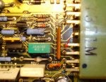
Indeed, it was almost impossible to note it......but the ECU had a blown
small trace on top layer close to the B-connector......which I have fixed now. I have attacched a photo of that.....

As I will have time to go to the repair shop, I will try again the board and
let you know the results....

Cheers!:D
Eon
 

Attachments

yes, as noted the diode will never blow before the trace. THANKS for photo, yours added to the ecu h3LL page.
the diode is good for 1 amp, (more with surge)

the trace is like 0.1amp max

acts just like a fuse. just jump it with 24ga wire.
its easy to do fix 5m.

need more help?

this fail is in the 10 ten. IMHO.
 
no need to throw $300 ECU at it,
not every-time.

put a 1/2 amp SB fuse there.

just in case the MAIN relay has issues.?
id use an inline fuse. off the shelf OTC.

this car was hot wired. or main has a short from battery to coil
or the coil is just plain old fashioned shorted.
check its coil carefully
they never fail but never say never. grin !
 
Discussion starter · #76 ·
Hello Kick,
yes I have jumped the small trace with a GAmp wire. So incredible poor
layout PCB design quality this ECU has. For automotive applications I would had expected more design-care....

However, I need to test the ECU....this will be during this week......

Btw....below I have some more questions:

no need to throw $300 ECU at it,
not every-time.

put a 1/2 amp SB fuse there.

On which line shal I have a 1/2 amp fuse?

just in case the MAIN relay has issues.?
id use an inline fuse. off the shelf OTC.

this car was hot wired. or main has a short from battery to coil
or the coil is just plain old fashioned shorted.

I think the repair shop guy, messed-up things before
to call me for help the first time....and the blown trace is an evidence....

check its coil carefully

Shall I simply check the MAIN fuse disconnected coil
between the correct pin of that if there is still continuity with a VM?
Or do you have other suggestions for this test?

they never fail but never say never. grin !
Thanks alot.
Cheers
Eon
 
i bet mech, cant prove it, hot wired the MAIN and blew up your ecu.

but using an ohm meter
remove main.
measure coil. 10 -40 ohms is range of val. can give exact if need be.
using Rx200 range of DVM.

put fuse between B15 in ECU and MAIN.
now more 60's era mech proof. (hot wire kings i call them)

the fuse is not needed if , you fire crazy mech and coil is reading correctly.

the ecu can not be protected 100% from all hot wire events.
how ever some cars 2010 have $3500 ecu that excell at that.

EG: injectors with AI , injector drivers (ecu can see you overload an injector and
then shuts it down. , almost idiot proof those are. (but then comes.....)????
the inputs are alread protected. they have 1 or 2k protection resistors.
but those outputs ARE NOT protected. NO WAY.

never never shunt or short any output of any ECU made on earth.
or any computer.

a 12volt battery with 500cca can blow anything to H3LL ( you can weld with it)
there is no ECU in the world that can protect from that .
only as the book says, "disconnect battery " before servicing EFI"

ECUs are better to day for sure.
 
look at another way

that trace is the fuse and saved the very very expensive deeper circuits.

sure DID.

you could replace that jumper with a modern Poly Fuse. biggest you can find. 100ma?
that be the modern way .

and were not invented in 88.(black sheet of paper for Mitsubishi ecu designs?)

they warm up and increase resistance then saves the damage, after that it cools and shorts.
the are really cool technology and are OTC.
 
Discussion starter · #79 ·
i bet mech, cant prove it, hot wired the MAIN and blew up your ecu.

but using an ohm meter
remove main.
measure coil. 10 -40 ohms is range of val. can give exact if need be.
using Rx200 range of DVM.

put fuse between B15 in ECU and MAIN.
now more 60's era mech proof. (hot wire kings i call them)

the fuse is not needed if , you fire crazy mech and coil is reading correctly.

the ecu can not be protected 100% from all hot wire events.
how ever some cars 2010 have $3500 ecu that excell at that.

EG: injectors with AI , injector drivers (ecu can see you overload an injector and
then shuts it down. , almost idiot proof those are. (but then comes.....)????
the inputs are alread protected. they have 1 or 2k protection resistors.
but those outputs ARE NOT protected. NO WAY.

never never shunt or short any output of any ECU made on earth.
or any computer.

a 12volt battery with 500cca can blow anything to H3LL ( you can weld with it)
there is no ECU in the world that can protect from that .
only as the book says, "disconnect battery " before servicing EFI"

ECUs are better to day for sure.
Sorry Kick,
could you please tell me the MAIN fuse pin wire color to know where is the
coil and where is the switch? Thanks

Cheers
Eon
 
ahhhh,
if you know where main is , right.? Next to mr, Green socket and has blue wires.....
it has 4 wires.
each is a diff color , pin # varsus by books, and GM and SUZ
but wire color rules
B15 drive. coil.
see relay , now make a drawing of what pins connect to
black-white and the blue pins.
now remove relay

now measure those 2 pins, for ohms zero is bad. 10 to 40 ohms, is ok
if ok
then put a 1/2 amp inline fuse inline of B15 blue
cut wire splice in fuse
or alternately
the jumper in the ecu , that you just put in, could have been, and inline fuse.
this will protect the ecu.

we dont really know who or what caused it but we are suspisious. huh?

how is that. partner.


Image
 
61 - 80 of 144 Posts